Hogwarts LED Display
A bit more magical
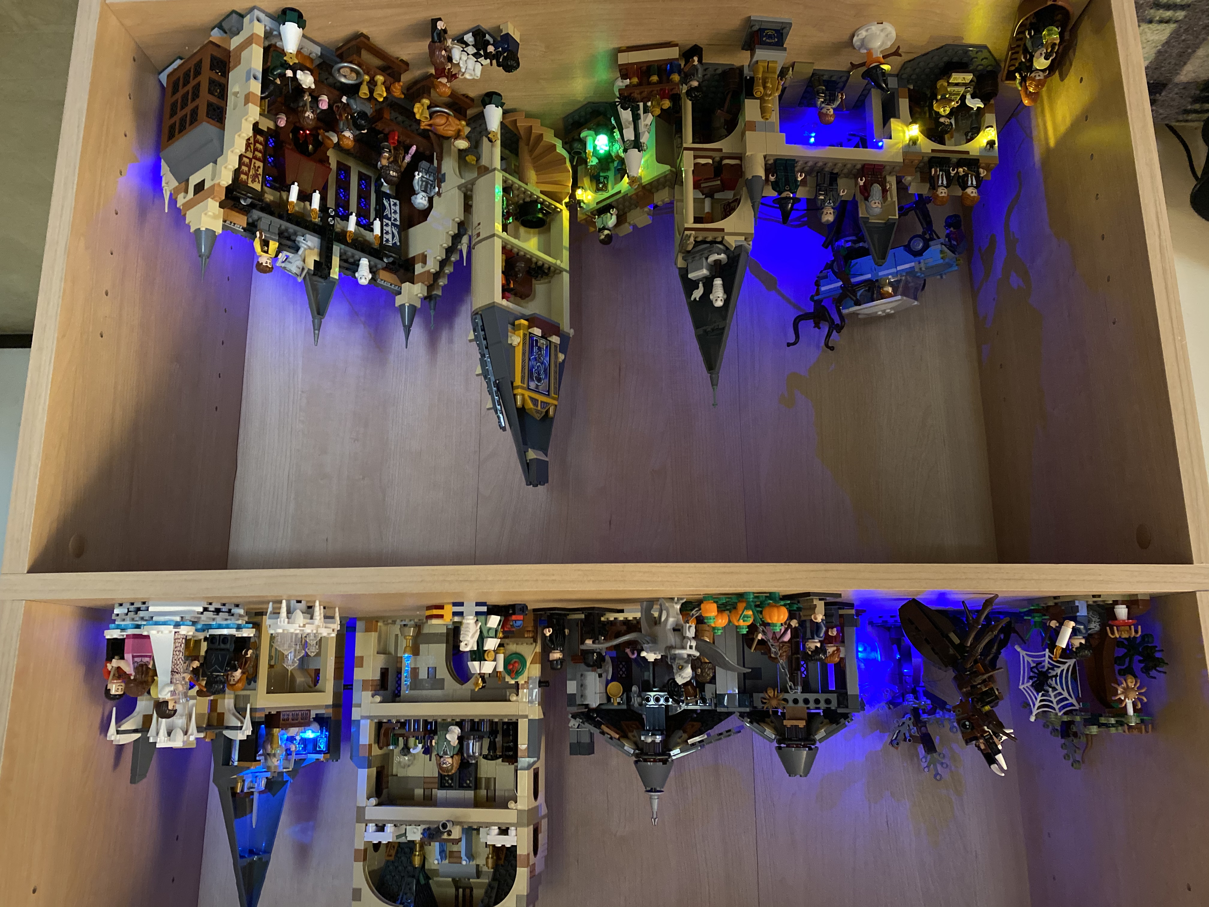
My wife collects Harry Potter Lego and has a nice setup for her Hogwarts Castle collection. She mentioned wanting to light it up in some way so it could be enjoyed in the evening. I took the idea further than she likely intended by designing and building an LED display for the castle. The display included 16 individual LEDs, an LED controller, and a 3D printed case to hold it all together.

Lights
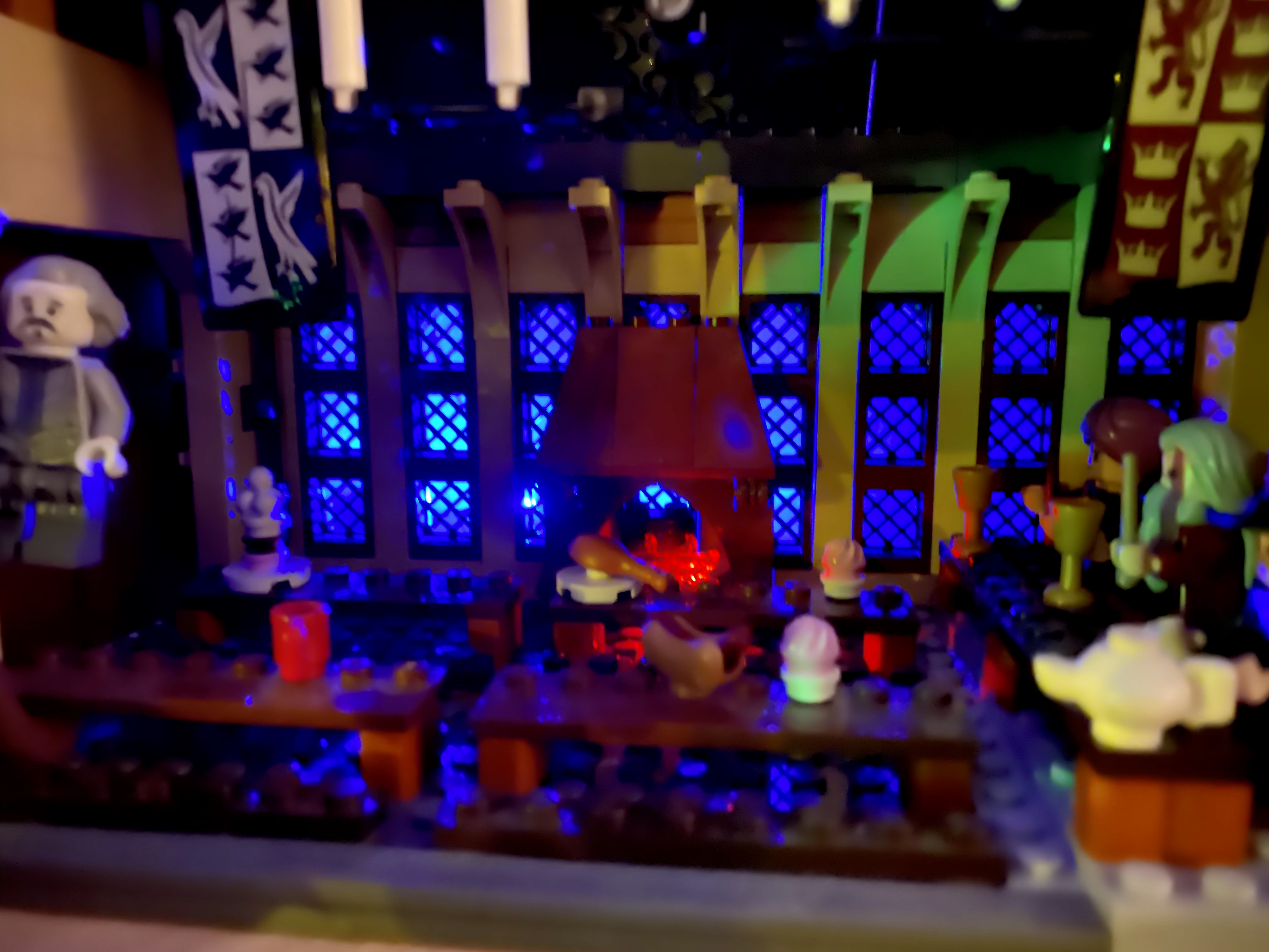
I started out by trying out some possible LED/Lego combinations to see what effects worked well. I used the Pico LEDs from Evan Designs since they are bright, incredibly tiny, and come pre-wired (a big time savings).
I mocked up a few possible combinations and it was clear that they would look very cool when added across the whole set.


I took stock of all of the LEDs I had on hand and planned out an arrangement for 16 individual lights.
Controller
It would have been simple to wire up all of the LEDs to a 9-volt battery with a switch and call it done. However, it seemed more fun to do a bit of extra-engineering and animate the lighting. I wanted to support flickering torches and fading magical effects. This required a programmable micro-controller capable of 5v analog output on 16 distinct channels. This is no trouble at all for most Arduino devices. I selected the Adafruit Metro Mini because it is small, cheap, and would fit nicely on the protoboards I had on hand.
I tested the Metro setup on a breadboard and validated the basic functionality with some test code. Then, I decided on a final layout for the components on the protoboard. I used Fritzing to create a mockup of the layout and a wiring diagram. Adafruit kindly provides a Fritzing library containing pretty much all of their components, including the Metro Mini.


I did it mainly as a way to learn more about the Fritzing application itself but I ended up referring to the diagram many times while soldering the components to the board.
Case
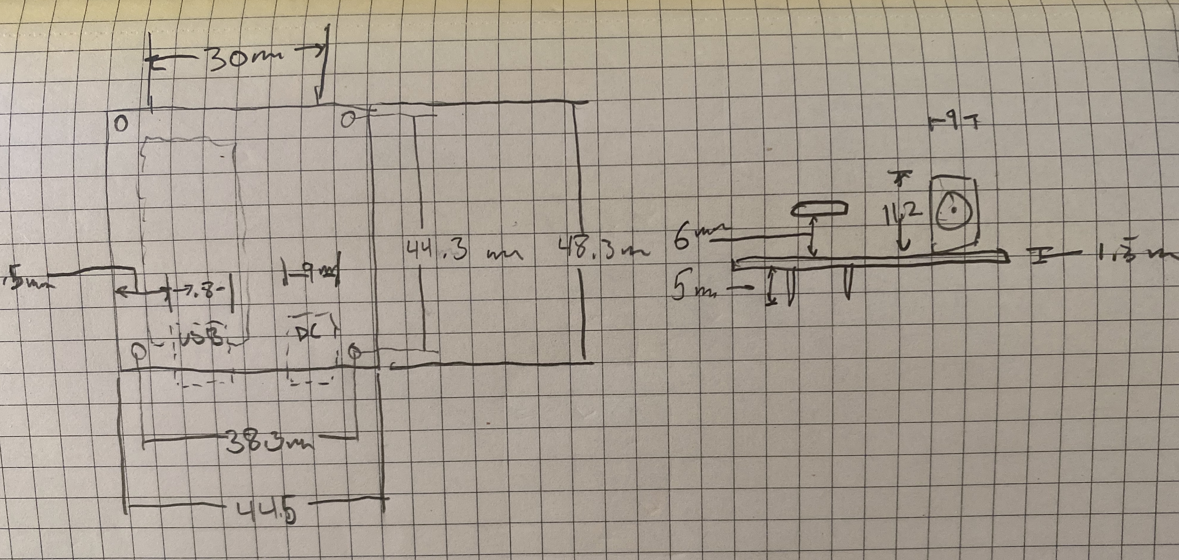
I also designed and 3D printed a case for all of the components. The case provides standoffs to mount the assembled board along with ports for power, USB, the switch, and the bundle of LED wires. The two halves snap together with some fillets on either side.
I started by measuring the dimensions of the various components and sketching out the layout. I took those measurements into Blender and reproduced the rough shape of the assembled board in 3D. From there I built the case parts around the rouged out shapes. At various times I test printed pieces of the case to verify the fit.
The final printed case works great and ties everything into a nice package.

Action
The last major piece of the project was writing code to control the LEDs. Everyone who has tinkered with an Arduino has written code to make an LED blink. It's the Arduino "Hello World". From there it's not too hard to flicker an LED like a candle with some calls to digitalWrite(pin, HIGH) and digitalWrite(pin, LOW) and some random delays.
However, an issue arises when you have many LEDs and you have the desire to run a sequenced animation for each one simultaneously. There are no native threads in Arduino code, no built-in multitasking. The oft-used delay() is a busy-wait which ties up the processor. A completely different approach was required to handle various modes of operation for the LEDs.
For each type of effect, I created a class with an Update() method to handle changing the LED illumination values over time. For a “fire” effect I used a random walk up and down the space of values (0 - 255):
class Fire {
  int pin;
  int currentValue;
  public:
  Fire(int ledPin) {
    pin = ledPin;
    pinMode(pin, OUTPUT);
    currentValue = 0;
  }
  void Update(unsigned long dt) {
    int delta = random(-5, 5);
    currentValue += delta;
    currentValue = constrain(currentValue, 0, 255);
    analogWrite(pin, currentValue);
  }
};
Representing each pin a a separate class made it easy to get a different animation for each instance of the effect and keep the code clean. Driving multiple LEDs with the same values results in a very obvious duplication of lighting across the display. Animating each one separately gives it a more organic feel.
I added effects for lamp Flicker and a pulsing Fade as well.
The main program initializes these classes for each of the LEDs it is controlling and then in the loop() it calls Update() on each instance passing in the delta time since the last call to Update(). Each instance can then schedule lighting changes at their own rate without worrying about a global delay() tying everything up.
It's a simple approach but it's not necessarily obvious when starting from most tutorial code.
You can view and download the complete Arduino sketch for this project on GitHub.
Assembly
It took several days of soldering to assemble all 16 LED wires, add connectors, and apply heat shrink tubing but it was worth it. When it came time to set up the display I was very glad to be able to easily swap LEDs from one pin to another.

The Result
It was a fun project to design and create and it resulted in an attractive addition to our Hogwarts display. Here is a video of the start-up sequence and a closer look at some of the scenes.